It took me a really long time to get this working correctly, so a quick and dirty article to preserve my effort for next time I need this and inevitably have to figure it out from scratch again...
#include "Arduino.h"
#include <nrf.h>

volatile bool rtc_triggered = false;
volatile int counter = 0;

void setupRTC(int seconds) {
    // Enable the low-frequency clock source
    NRF_CLOCK->LFCLKSRC = CLOCK_LFCLKSRC_SRC_RC << CLOCK_LFCLKSRC_SRC_Pos;
    NRF_CLOCK->TASKS_LFCLKSTART = 1;

    // Wait for the external oscillator to start up
    while (NRF_CLOCK->EVENTS_LFCLKSTARTED == 0);
    NRF_CLOCK->EVENTS_LFCLKSTARTED = 0;

    // Configure RTC
    NRF_RTC0->PRESCALER = 1023; //freq 32768/1024 = 32 Hz
    NRF_RTC0->EVTENSET = RTC_EVTENSET_COMPARE0_Msk; // Enable compare0 event
    NRF_RTC0->INTENSET = RTC_INTENSET_COMPARE0_Msk; // Enable compare0 interrupt
    NRF_RTC0->CC[0] = seconds*32; // Set compare value to 32 ticks (1 second)

    // Enable RTC interrupt in NVIC
    NVIC_EnableIRQ(RTC0_IRQn);

    // Start RTC
    NRF_RTC0->TASKS_START = 1;
}

void enterSleep() {
    rtc_triggered = false;
    // Clear any pending events
    NRF_RTC0->EVENTS_COMPARE[0] = 0;

    // Enable deep sleep mode
    SCB->SCR |= SCB_SCR_SLEEPDEEP_Msk;

    // Enter sleep mode and stay there until RTC triggers
    while (!rtc_triggered) {
        __WFE();
        __SEV();
        __WFE();
    }
}

// RTC0 interrupt handler
extern "C" void RTC0_IRQHandler(void) {
    if (NRF_RTC0->EVENTS_COMPARE[0]) {
        NRF_RTC0->EVENTS_COMPARE[0] = 0; // Clear compare event
        NRF_RTC0->TASKS_CLEAR = 1; // Clear counter
        rtc_triggered = true;  // Set flag to exit sleep
    }
}

void setup() {
    Serial.begin(115200);
    setupRTC(1);
}

void loop() {
    Serial.println("Awake - doing work");

    Serial.print("Current RTC COUNTER value: ");
    Serial.println(NRF_RTC0->COUNTER);

    Serial.print("Current RTC PRESCALER value: ");
    Serial.println(NRF_RTC0->PRESCALER);


    //START Do some real work here....
    counter++;
    Serial.print("Counter: ");
    Serial.println(counter);
    //END Do some real work here....

    Serial.println("Entering sleep for 1 second");
    Serial.flush(); // Ensure all serial data is sent before sleeping

    enterSleep();
}
Main.cpp
; PlatformIO Project Configuration File
;
;   Build options: build flags, source filter
;   Upload options: custom upload port, speed and extra flags
;   Library options: dependencies, extra library storages
;   Advanced options: extra scripting
;
; Please visit documentation for the other options and examples
; https://docs.platformio.org/page/projectconf.html

[env:sparkfun_pro_nrf52840_mini]
platform = nordicnrf52
board = sparkfun_pro_nrf52840_mini
framework = arduino
platformio.ini
(The above assumes the same environment configuration as the section 'PlatformIO Config for NRF5' here: https://blog.thedevforge.com/weact-studio-1-54-epaper-module-spi-interface-with-nrf5340/
Overview of the Code
The code configures the RTC peripheral to generate periodic interrupts every second, triggering the micro-controller to wake up from a low-power sleep mode. During each wake cycle, it performs some work (incrementing a counter and printing debug information), then re-enters sleep mode for another second. This is particularly useful for battery-powered devices where conserving energy is critical.
Key features of the code:
- Low-Frequency Clock (LFCLK) : The RTC relies on the 32.768 kHz low-frequency clock, which is ideal for low-power applications.
- Prescaler Configuration : The prescaler divides the LFCLK frequency to achieve a desired tick rate.
- Interrupt Handling : The RTC generates interrupts at regular intervals, enabling precise timing.
- Deep Sleep Mode : The microcontroller enters a low-power state (
__WFE()), reducing energy consumption until the next interrupt.
Understanding the Prescaler
One of the most important aspects of this code is the prescaler configuration. The prescaler determines how often the RTC increments its counter by dividing the input clock frequency. In this case:
NRF_RTC0->PRESCALER = 1023;What Does This Mean?
- The LFCLK runs at 32,768 Hz .
- The prescaler divides this frequency by
(PRESCALER + 1)
This means the RTC increments its counter 32 times per second , giving us a resolution of approximately 31.25 milliseconds per tick .
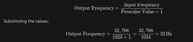
Maximum Prescaler Value
Since the prescaler is 12 bits wide , its maximum value is:

At this maximum value, the output frequency would be:

This results in a tick interval of 125 milliseconds .
Breaking Down the Code
1. Setting Up the RTC
The setupRTC function initializes the RTC peripheral:
- Enabling the LFCLK : The 32.768 kHz clock source is enabled using the
NRF_CLOCKperipheral. - Configuring the Prescaler : As discussed, the prescaler is set to 1023 to achieve a 32 Hz tick rate.
- Setting the Compare Value : The compare register (
CC[0]) is configured to trigger an interrupt after a specified number of ticks. For example, setting it toseconds * 32ensures an interrupt everysecondsseconds. - Enabling Interrupts : The RTC interrupt is enabled in the NVIC (Nested Vectored Interrupt Controller).
NRF_RTC0->CC[0] = seconds * 32; // Set compare value for 1-second intervals2. Entering Sleep Mode
The enterSleep function puts the microcontroller into a deep sleep mode:
- Clearing Events : Any pending RTC events are cleared to avoid spurious wake-ups.
- Enabling Deep Sleep : The
SCB_SCR_SLEEPDEEP_Mskbit is set to enable deep sleep. - Waiting for Interrupt : The
__WFE()(Wait For Event) instruction halts the CPU until the RTC interrupt occurs.
while (!rtc_triggered) {
    __WFE();
    __SEV();
    __WFE();
}
The double __WFE() pattern is used to handle edge cases where spurious wake-ups might occur.
1. First __WFE()
- The first
__WFE()puts the processor into a low-power state. - If no event is pending, the processor will remain asleep until an event occurs (e.g., an RTC interrupt).
2. __SEV()
- The
__SEV()(Send Event) instruction generates a global event signal that wakes up all cores in a multi-core system (or ensures the current core is ready to process events). - This ensures that any pending events are properly acknowledged before proceeding.
3. Second __WFE()
- The second
__WFE()clears the event flag that was set by__SEV(). - Without this second
__WFE(), the processor might immediately wake up again due to the lingering event flag, even if no real event occurred. This could lead to unintended behavior, such as repeatedly exiting sleep mode prematurely.
By using this sequence (__WFE(); __SEV(); __WFE();), you ensure that:
- The processor only wakes up when a real event occurs.
- Any spurious wake-ups caused by leftover event flags are avoided.
3. Handling Interrupts
The RTC0_IRQHandler function handles the RTC interrupt:
- It clears the compare event and resets the RTC counter.
- It sets the
rtc_triggeredflag to signal the main loop to exit sleep mode.
if (NRF_RTC0->EVENTS_COMPARE[0]) {
    NRF_RTC0->EVENTS_COMPARE[0] = 0; // Clear compare event
    NRF_RTC0->TASKS_CLEAR = 1;       // Clear counter
    rtc_triggered = true;            // Signal wake-up
}
4. Main Loop
In the loop function:
- The micro-controller performs "work" (e.g., incrementing a counter).
- Debug information is printed to the serial monitor.
- The device re-enters sleep mode after completing its tasks.
Addendum
I have refactored the above code into a nice re-usable library
To use the library, unzip and put into the lib folder. Eg:
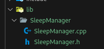
Then, in your Platformio.ini file add
lib_extra_dirs = lib#include "Arduino.h"
#include "SleepManager.h"
#define LED_PIN LED_BLUE
SleepManager sleepManager;
int counter = 0;
void setup() {
// Configure LED
pinMode(LED_PIN, OUTPUT);
digitalWrite(LED_PIN, LOW);
Serial.begin(115200);
sleepManager.init(1); // Set sleep time to 1 second
}
void loop() {
Serial.println("Awake - doing work");
Serial.print("Current RTC COUNTER value: ");
Serial.println(sleepManager.getRtcCounter());
Serial.print("Current RTC PRESCALER value: ");
Serial.println(sleepManager.getRtcPrescaler());
//START Do some real work here....
counter++;
Serial.print("Counter: ");
Serial.println(counter);
//END Do some real work here....
Serial.println("Entering sleep for 1 second");
Serial.flush(); // Ensure all serial data is sent before sleeping
sleepManager.enterSleep();
// Toggle the LED pin after waking up
digitalWrite(LED_PIN, !digitalRead(LED_PIN));
}Main.cpp
Reference Documentation
nRF52840 Product Specification v1.11
Power usage in mAh during sleep and run mode.
The above video shows the power usage on this board during sleep and run mode. Keep in mind in run mode the LED is toggled on so that will increase power usage as well.
